Globally, the assembly design as an integrated system engineering process has not demonstrated significant improvement for decades relative to other engineering processes. With the advent of 2D computer based drafting came the need for unique experience to operate the CAD systems starting the separation of the engineering thought process from the drawing creation and update automation. Engineers have historically best conceptualized in 2D creating multiple views of an assembly idea in order to start the iterative approach to finalizing a design concept believed to achieve product requirements. Many 2D layouts included a significant number of views with detailed notes documenting a large amount of the product engineers ideas to pass on to others in the product development process.
As a result of this approach, 2D layout approaches made it difficult to completely capture the assembly design in the context of how surfaces will interact when parts come in contact. This in turn required prototyping of parts and assemble them for the first time in order to conduct the first real assessment as to the success of that assembly design with respect to product Key Characteristics.
The ongoing development of CAD systems into full solids-based 3D design capture tools gave additional insight as to the parts in final assembled positions, but still could not confirm that the parts as placed by the designer in the CAD system were in fact consistent with what would be the result when actual parts were assembled. The CAD systems
allow for the concept of ‘interference’ checking, but the accuracy of the interference behavior was totally dependent on the placement of the parts in assembled position by the designer. The CAD systems have not been able to provide adequate assembly methods that guarantee consistency with actual final assembly behaviors.
Given the part based nature of creating and approving drawings, the automation of drawings has become a primary driver in product development procedures. Drawings have a significant number of assessments provided by other experienced designers, quality inspectors and sometimes manufacturing experts, yet still have a high probability that there exists very significant errors that will directly impact the manufacturability of the parts and assemblies in addition to creating potential product performance defects.
In order to analyze assemblies for compliance to KC and manufacturability requirements, a large amount of specialist effort has been needed to reverse engineer the assembly functional design intent and combine that with the functional feature geometric dimensioning and tolerancing schemes. These specialists require additional knowledge of the assembly and assembly analysis modeling techniques to provide reasonably accurate assessments of the assembly design.
Suppliers of parts and sub-assembly components many times are frustrated with the inconsistencies between what the designer documented in drawings vs. what actually works in the final assembly conditions. This has caused an abnormally large number of iterations between designers and suppliers trying to rectify solutions that many times do not address the true root cause of the problem. This directly impacts what some companies call the ‘time to quality’ which is a measure of how fast a product can ramp up to full expected quality levels in full manufacturing volumes. It is very common that design flaws drive most of the time to quality since they are found as problems in manufacturing but are identified as design errors requiring extensive engineering changes in design documentation, further driving up cost and schedule delays. It is well documented that as much as 50% of engineering changes made to part designs are the direct result of dimensioning and tolerancing errors in the drawings that were not previously found.
Assembly Engineering Missing Fundamentals involving Manufacturing Variation:
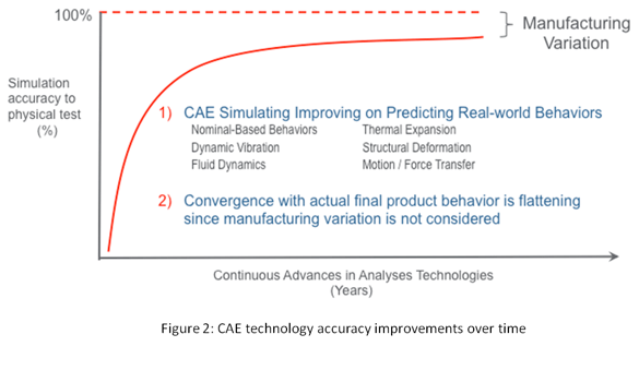
Extremely large amounts of investment have gone into the creation of sophisticated design verification and simulation tools in order to validate a design’s robustness to KC’s prior to physical testing. Over the past 20 years CAE companies have not only improved the accuracy of co-relation between predictions and physical test, but have also made that effort significantly less with automated analysis model creation and optimized solver technologies. See Figure 2. In the past several years there has been a clear flattening of the convergence between required accuracy of assembly behaviors and physically measured behaviors given no consideration has been made for actual manufacturing and assembly clearance error.
It is interesting to note that many designs have been given a tolerance, or allowance, for deviations from a nominally perfect design. In fact, the concept of a nominally perfect design has created confusion since parts are produced with inherently imperfect processes and assembled in imperfect positions. This is a fundamental concern for robust assembly design and must be considered not only prior to manufacturing but at the beginning of the conceptual design process.
CAD Assembly Design Verification – Where is it?
The CAD industry has also made great strides in improving the effectiveness of product development processes. The attention has been on part level design authoring, editing, documentation and data management leaving the automation of robust assembly design methods severely behind the power curve. Companies, in particular design managers, assume that because the parts are designed in the CAD system and assembled in the CAD system that the assembly design is basically correct. Design reviews are very common as a method to try to verify an assembly design, but the ability to effectively see the behavior of the assembly under its imperfect conditions escapes even the best design review meetings.

A typical scenario is that a multi-disciplined product development team may sit in a meeting looking over multiple cross sections of an assembly design manually looking for any areas of concern with respect to part alignment, unexpected interferences or clearances between parts, and other potentially flawed alignments of critical interfaces. This process does not, nor can it not provide a quantitative assessment of the risk existing in an assembly design’s capability to meet the expected performance requirements.
Rapid prototyping has added an additional false sense of security to the verification of a robust assembly design. Most rapid prototyping systems can create amazingly accurate parts that can be assembled by an operator but can only give a small amount of additional verification confidence to the robust assembly problem.
Assembly Engineering Training – Where is it?
Many companies expect that graduating engineers have many of the basic educational foundation for the basic design creation, analysis and manufacturing of small assemblies. In fact, there are very few universities world wide with undergraduate engineering programs that even address anything beyond part design, some part centric analysis, like structure and thermal analysis, along with a very basic understanding of kinematic design of simple systems. The academic accreditation of many universities is based on criteria that does not place enough importance on the fact that engineers will most likely be designing assembled systems, not just parts, but even many of the professors in universities only have a limited amount of experience in assembly design optimization.
Different industry standards organizations, like the American National Standards Institute (ANSI) which sponsor the American Society of Mechanical Engineers (ASME), have in their objectives to create standards regarding proper design, construction and testing of many mechanical devices, however, there exists very little usable standards information for the design of robust assemblies. The ASME in North America and the International Standards Organization both have standards addressing the ‘correct’ approaches for creating functionally effective geometric dimensioning and tolerancing schemes (GD&T) on parts but have very little reference to the part functions within an assembly design. In fact, the GD&T standards in both organizations are not in agreement from a design philosophy standpoint nor on the structure of the standards documents themselves.
Various committees made up of academic, government and industry representatives have spent the past 30 years evolving complicated documents that have created a totally new language with unique symbology, rules, guidelines and even ways to represent this language on drawings and/or 3D models. As with any new language, there must be some original foundation, which in this case is a mathematical foundation of exact constraint systems. However, the focus of the GD&T standards documents has been more about documenting a functional design intention on drawings in a way that is theoretically unambiguous for design, manufacturing and quality engineers to completely understand the requirements the same way. In fact, just the opposite has occurred.

A substantial amount of information in the standards has evolved through committee negotiations, rather than exclusively on the merit of the engineering precision, leaving these standards so difficult to train that very few individuals in a company are considered well versed. Per discussions with many of the standards committees members, it has been clarified that the standards are for properly documenting the functional design features on parts with no accountability for wether those same features actually work in an assembly system.
University Curriculum Example:
An example of how little is taught in the university for assembly systems is described in the 2 part model shown in Figure 5. A base part consisting of an L-shaped plate with 2 circular pins is used to assemble a flat plate with a hole slightly larger than the mating pin on the base part and a slot slightly wider than the other pin diameter on the base part. This is one of the most common ways to assemble to simple flat parts to each other. The diagram on the left of the graphic is used to express the logical graph or exact constraint state of the assembly. That is, once the parts are put together, will they go together without binding and will they not have too much clearance between the pins and the holes to allow the parts to still ‘move around’.
The table in the bottom of the graphic shows a relationship between the symbols in the logical graph, the parts and the amount of movement, or degrees of freedom, that actually can exist in the real physical world when assembling these 2 parts. The extent of expanding on this basic concept to include a much larger set of assembly constraint designs is virtually non-existent in university curriculum leaving engineering graduates with very little background in the subject.

Assembly Constraints are Complicated:
When looking comprehensively at the different types of assembly constraints that can exist in the real world we need to look at all the different combinations of surface/features that can actually assemble to each other and how those interfaces behave with respect to exact constraints or degrees of freedom. As an example, CAD systems have the ability to accurately represent every kind of surface that exists in the real physical world. When all different surface types are potentially in contact with any of the remaining surface types, we see there is a very large number of possible combinations of contacts that can exist.
When we combine the fact that many surfaces don’t just simply touch, but rather float around within another surface, then we get an entire new set of possible conditions that might exist in any assembled product. There are a large number of surface/feature types including points, lines, arcs, planes, holes, slots, cones, spheres, toroids, tabs, helical, asymmetric and others. If we include the fact that when a pin is in a hole, then the alignment of the two features can be along the same center axis, it can be contact at a tangential location or can be floating around in a random manner.
Once we look at all the possible combination and permutations of what can really exist in and assembly there are recognized over 250 unique assembly constraints. To put this in perspective most CAD systems have less than 15 different kinds of assembly constraints of which a smaller set of these are primarily used by designers and engineers when ‘capturing’ the assembly design intent. There is clearly a serious deficiency in the CAD systems capability to assist in this area. This leads us to the need for a more comprehensive, mathematically based and physics validated approach to assembly design.

Industry Based Training for Assembly Engineering
Since the academic and industry standards organizations have not been able to fully address this deficiency in assembly design education, it has been left to the various industries to implement their own engineering skills development in this area. Unfortunately, industries typically don’t invest in training what is really needed at the fundamental levels, but rather focus on making employees jobs easier and on trying to implement popular processes touted to resolve many of the product quality and cost problems that result from poor assembly designs. Design for Six Sigma, Design for Manufacture and Assembly, Model Based Design, etc., are all good ideas that will in fact improve companies ability to get better, but none of these practices provide for a valid, analytical based method, for analyzing an assembly design for robustness.
From a business perspective, training employees is very costly and that investment is not usually focused on the best areas to train. Due to the complexity of CAD and data management systems, along with the constant updating and dependencies between these systems, much of the engineering training budget in companies is spent on keeping the organizations capable of using part design capture tools and the associated way to version, archive and re-use that information. Training for analysis, especially assembly design analysis, is left as a lower priority and many times does not make the budget cut.
Lack of Assembly Engineering Based GD&T Training
The training available for functional GD&T has been well developed by many individuals who have a good understanding of the standards documents themselves. The focus of the training materials is primarily on applying the ‘rules’ defined in the standards and does not give significant coverage to the assembly design process as a driver for establishing the actual part functional feature set and the criticality of each functional feature to the assembly design requirements. Some training curriculum associated with GD&T may discuss simplified 1-D Tolerance Stack-up (1D SU) to relate the GD&T settings to an assembly requirement, however, 1D SU analysis is inconsistent with the intent of GD&T standards, which is to fully define functional feature controls for surfaces on a 3D part. The oversimplification of the assembly functional needs to a 1 Dimensional set of assembly requirements has proven to be insufficient to guarantee assemblies will function as designed even given GD&T that is ‘correct’ per the standards.
The evolution of the GD&T standards has led to a current cottage industry of training companies who competently train the compliance to the standards, but struggle to train the critical thinking necessary to apply GD&T in the context of a robust assembly design, which is the ultimate goal for the function of most parts designs.
GD&T Standards Based on a Very Complex Language
In order to put the GD&T standards training issue in perspective, the definition of a hole feature is described in the Figure 7. The standards are well organized with respect to defining the size, location, orientation and form of a surface by describing ‘Tools’ that can be used for each of these definitions. The challenge is in understanding why a feature needs to be defined in a very specific way which normally requires a clear understanding of what drives the functional need for those controls from an assembly functional need. One of the most basic assembly constraint approaches is using holes with pins to enable for parts to go together, and if necessary, come apart again for various assembly process, part replacement, maintainability or other legitimate product capability needs.