Why Model-Based Definition (MBD) Is the Future of Product Design
Key Takeaways
- MBD replaces 2D drawings with a single 3D source of truth, embedding crucial product and manufacturing information (PMI) directly into CAD models.
- Well-executed MBD streamlines workflows across design, manufacturing, and inspection, reducing errors, rework, and time-to-market.
- A successful MBD rollout depends on standards, training, and tool integration, guided by a phased MBx roadmap.
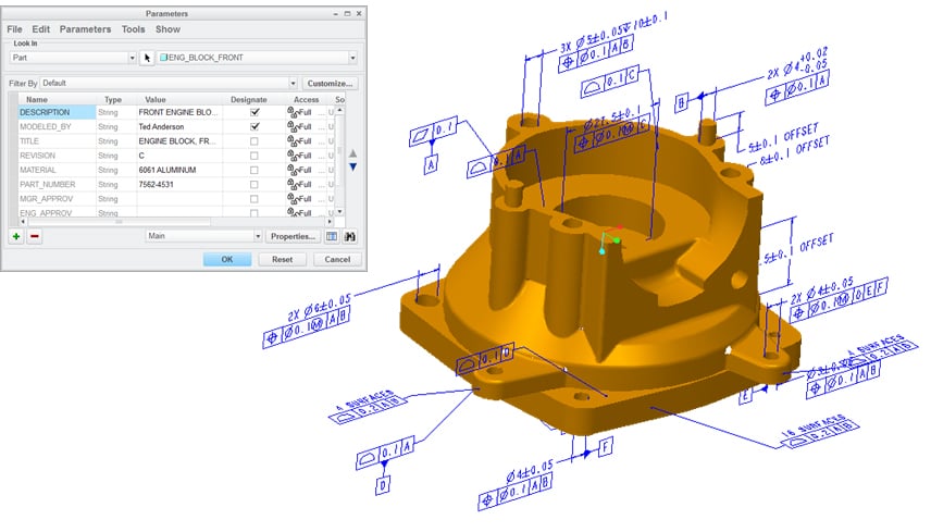
Gone are the days of relying solely on 2D drawings to communicate product requirements. Manufacturers are instead using Model-Based Definition (MBD) to embed GD&T, materials, and manufacturing information directly into the 3D CAD model. This approach creates a single source of truth for design, engineering, production, and inspection teams.
When implemented thoughtfully, MBD streamlines workflows, reduces documentation errors, and strengthens cross-functional collaboration. But achieving success in this new era of product design requires new tools and a model-based (MBx) strategy that aligns people, processes, and technology every step of the way.
How Well-Executed MBD Streamlines Design Workflows
Model-Based Definition has the power to transform the entire product development process into a more connected, accurate, and efficient workflow.
Single Source of Truth
MBD eliminates the need for separate 2D drawings by embedding all crucial Product Manufacturing Information (PMI) directly into the 3D model. PMI includes dimensions, tolerances, materials, surface finishes, and other specifications that define how a part should be manufactured and inspected. Consolidating this information reduces manual data entry, version mismatches, and interpretation errors.
Faster Downstream Handoffs
Because CAM, CMM, and PLM systems can read PMI directly from the model, teams can skip time-consuming document translations. The result is quicker setup for tooling, faster inspection planning, and better alignment across engineering, manufacturing, and quality assurance.
Automated Change Propagation
With MBD, design changes automatically update related documentation, tooling paths, and inspection criteria. It’s all connected, reducing the risk of teams accidentally using outdated files and minimizes manual rework due to overlooked changes.
Reducing Documentation Errors with Embedded PMI
One of the biggest advantages of Model-Based Definition is its role in reducing documentation errors. Embedding PMI directly into the 3D model ensures that all teams work from the same authoritative, up-to-date data.
By embedding Geometric Dimensioning and Tolerancing (GD&T) notation in 3D models, teams drastically reduce the risk of misinterpretation. Engineers, machinists, and inspectors see the same feature control frames attached to the relevant features. Traditional 2D callouts simply can’t provide this level of context for tolerance information.
MBD also reduces the risks associated with relying on separate 2D PDFs for communication on the shop floor. These standalone 2D drawing files are prone to version mismatches and distribution errors. By using a single, managed CAD file with embedded PMI, teams always reference the most current model.
Finally, modern model-based inspection tools can read PMI directly from the 3D model and immediately flag discrepancies between design intent and as-built parts. Identifying potential issues earlier in the production process reduces costly rework, ensures compliance, and supports faster approvals during design reviews.
Risks of Poor MBD Implementation
Although its many benefits make it worth the effort, transitioning to a fully model-based workflow comes with challenges. Be aware of these common pitfalls:
- Incomplete PMI Annotation: If crucial details are missing from the model, downstream teams may be forced to guess or revert to legacy documentation, reintroducing risk and confusion.
- Toolchain Gaps: Incompatible or poorly integrated CAD, CAM, and CMM platforms can break the digital thread, forcing manual workarounds and diminishing the value of MBD.
- Insufficient PLM Integration: Without a well-structured PLM system, teams may duplicate efforts or create disconnected model versions. Even in model-based enterprises, offline work that isn’t synced back into the system creates versioning risks.
- Supply Chain Incompatibility: Even if your organization adopts MBD, your suppliers may still depend on 2D or hybrid workflows. Successful collaboration with suppliers often requires detailed planning and use of viewer tools and/or transitional formats like STEP AP242.
- Cultural Resistance: Designers, machinists, or inspectors accustomed to 2D prints may resist change, defaulting to outdated workflows and introducing redundant documentation.
MBx Implementation Stages
Implementing a model-based approach isn’t an overnight shift. Organizations often progress through different levels of model-based maturity, such as:
Model-Based Drawings (MBDw)
This transitional stage combines the 3D model with automatically generated 2D views. It allows teams to maintain familiar drawing practices while beginning to embed PMI in the 3D model. MBDw builds stakeholder confidence and helps bridge the gap between traditional documentation and fully digital workflows.
Model-Based Definition (MBD)
At this stage, the 3D CAD model becomes the single source of truth and contractual authority. PMI, including dimensions, tolerances, materials, and notes, is fully embedded in the model. There is no longer a need for separate 2D drawings.
Model-Based Enterprise (MBE)
The most advanced stage connects the 3D model to every phase of the product lifecycle. Design, CAM, inspection, quality, and suppliers all work from the same digital model. This enables a seamless digital thread, enhances traceability, and supports automation throughout the value chain.
Ultimately, each organization's path toward becoming a model-based enterprise will look different. There’s no one-size-fits-all approach to MBD adoption.
Best Practices for Successful MBD Rollout
Adopting Model-Based Definition requires careful planning, technical alignment, and team buy-in. The “crawl, walk, run” approach offers a proven path to scalable success:
Crawl: Start with Pilot Projects
Begin with low-risk parts and assemblies. Use them to validate your tools, refine your processes, and prove internal value before expanding.
Walk: Cross-Functional Training and Standards Adoption
Train design, manufacturing, QA, and suppliers on reading and authoring 3D PMI. Align on standards like ASME Y14.41, STEP AP242, and QIF to ensure interoperability.
Run: Toolchain Integration and Full Deployment
Verify that CAD exports flow cleanly into downstream systems like CAM, CMM, and PLM. Once stable, scale MBD across more programs, using lessons learned to guide process improvement.
A phased strategy helps organizations build momentum while minimizing risk.
Key Tools and Technologies
You need the right toolchain to support 3D model creation, validation, and downstream consumption. Below is a breakdown of core tool categories and how they support an effective MBD workflow:
|
Tool Category |
Examples |
Role in MBD Workflow |
|
CAD Platforms |
PTC Creo, Siemens NX, Dassault CATIA |
Create 3D models with embedded Product Manufacturing Information (PMI) and GD&T |
|
Validation Software |
Capvidia MBDVidia, Verisurf, 3DTransVidia |
Check performance of PMI between CAD and neutral formats like STEP AP242 and QIF |
|
Inspection Automation |
CMM software |
Automatically generate inspection routines from model-based PMI for QIF- or STEP-ready CMMs |
|
PLM Systems |
Siemens Teamcenter, PTC Windchill, Dassault ENOVIA |
Manage version control, access, and traceability of MBD data across teams |
When all tools are aligned around PMI standards like QIF and STEP AP242, teams can unlock the full value of MBD across design, production, and inspection.
Next Steps Toward a Model-Based Enterprise
Model-Based Definition offers real, measurable gains in speed, accuracy, and cross-functional collaboration. A successful rollout requires a structured MBx roadmap with considerations for technology and training.
Sigmetrix offers expert-led courses, interactive labs, and community support on MBD best practices. If you’re looking to build your team’s MBD knowledge and skills,