What is GD&T?
A design model is an idealized representation of a part design. However, the design model by itself does not fully define the design. Due to imperfections in manufacturing and inspection processes, physical parts never match the design model exactly. A fundamental part of GD&T basics is specifying how much the part features may deviate from their theoretically exact geometry (as defined in the design model).
Geometric dimensioning and tolerancing, often referred to as GD&T, is a symbolic language used on engineering drawings and models to define the allowable deviation of feature geometry. The language of GD&T consists of dimensions, tolerances, symbols, definitions, rules, and conventions that can be used to precisely communicate the functional requirements for the location, orientation, size, and form of each feature of the design model. Thus, GD&T is an exact language that enables designers to “say what they mean” with regard to their design models. Production can then use the language to understand the design intent and inspection looks to the language to determine set up requirements.
GD&T Basics as a standard for assembly design & production:
In order for any language to be effective, it must be based on a common standard. ASME and ISO both have standards related to the application and use of GD&T. The ASME standards are generally used by U.S. companies while the ISO standards are commonly used by European companies. Within each of those organizations there are several standards that are applicable to the topic of GD&T. Furthermore, each standard is periodically revised, with each version of the standard identified by the year of its acceptance. GD&T Advisor v1.2 is based on the following standards:
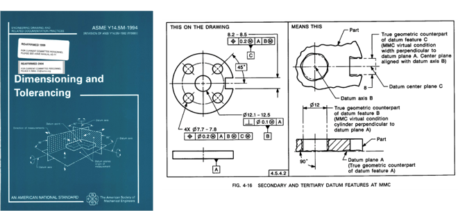
• ASME Y14.5M-1994 Dimensioning and Tolerancing – Defines the usage and meaning of geometric tolerances and related topics
• ASME Y14.41-2003 Digital Product Definition Data Practices – Defines the rules for displaying of annotations on the design model