
General Approach to Applying GD&T to a Design Model
In order to understand a qualitative application of GD&T to a production environment, one must understand the design model. A design model consists of a collection of geometric shapes, referred to as features. In a completed design, the geometry of the feature must be defined and the deviation of its geometry attributes (e.g., location, orientation, size, and form) must be constrained. There are two common approaches to constraining the deviation of the geometry attributes of the features in the design model. GD&T may be applied to each feature based on how the part functions or it may be based on how the part is manufactured. It is generally considered best practice for application of GD&T based on part function.
Step 1: Application of GD&T with established Datum Reference.
The first step in applying GD&T to a design model is to establish a datum reference frame (DRF). The first datum reference frame that is established is called the predominant datum reference frame. In a functional approach to GD&T, the surfaces that orient and locate the part in its assembly are typically used as the datum features that are used to establish the predominant DRF. There are also additional considerations for datum feature selection:
- Manufacturing considerations – You may choose to select the surfaces that orient and locate the part in the machining fixture as the datum features.
- Inspection considerations – You may choose to select the surfaces that orient and locate the part during the inspection process as the datum features.
Step 2: Application of GD&T to constrain attributes of features
Once the predominant DRF has been established, you can use GD&T to constrain the geometry attributes of each feature in the model with respect to that DRF based on function. In complex parts it may be necessary to establish multiple DRFs, but ultimately all features in the part must be constrained, either directly or indirectly, to the predominant DRF. GD&T Advisor software by Sigmetrix, provides convenient tools for defining the features on your part, applying GD&T to those features, and then evaluating each feature and the applied GD&T on the feature to determine whether all of the geometry attributes of the feature are fully constrained.
The table below shows the geometric characteristic symbols that are used to specify the geometric limits of deviation for a feature in the ASME Y14.5M-1994 standard.
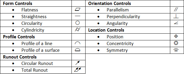
The geometric characteristic symbol, along with a tolerance value, modifying symbols, and a datum reference frame are grouped together in a feature control frame as shown below.
The feature control frame, sometimes referred to as a GD&T callout, defines the allowable feature deviation based feature function and design intent.
Practical Usage Example:
Consider the latching claw part shown here. This part is a component in a seat latching mechanism. The large planar surface is mounted flush with a planar surface on another part and is labeled as datum feature A. The large hole is a pivot hole for the claw, representing an important functional feature and is labeled as datum feature B. The small flat plane on the claw tip is the location where the claw makes contact with a striker bar to ensure the seat is secure to the vehicle frame and is labeled as datum feature C. There are several other functional features. These features should be controlled with reference to the mounting features A, B, and C. All of the remaining features for this part are less important and are controlled with general profile tolerance that can be found on a note.
Some of the key reasons for using GD&T include: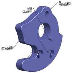
1.Provides a precise and consistent method for communicating design intent
2.Establishes a coordinate system (that references the datum features) for inspection and manufacturing
3.Reduces the need to explain complex requirements
4.Facilitates and simplifies gaging requirements
5.Identifies critical-to-function features
6.Simplifies tolerance analysis
Whilst there are many ways to calculate all of the data needed to produce the variances allowed within the part itself, those calculations can be time consuming and less accurate than using an integrated Tolereance Analysis Software such as CETOL 6 Sigma, or GD&T Advisor by Sigmetrix. The solution used in your environment will effect your overall production costs and quality matrixes. By choosing a software that integrates with the CAD system your team already uses (CREO, SOLIDWORKS, CATIA) – timing and accuracy are achieved early in the product design & engineering phase.